오늘은 phong shading, 정확히는 per-pixel lighting을 살펴보자.
phong shading은 per-pixel lighting에 추가적으로 다른 개념들이 사용된 셰이딩 방법이지만, 일단은 편의를 위해 phong shading이라고 표현하겠다.

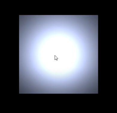
지난번 글에서 우리의 파이프라인의 point light에 한가지 문제가 있음을 언급했다.

이 사진을 보면 이해가 빠르다. 바로 빛이 거리의 영향을 받지 않는 문제이다.
그러나 우리는 분명 지난 시간에 거리에 따른 빛의 명암을 구현했는데, 이게 무슨 일일까?

물체를 기울여보면 그 문제의 원인에 대해 대략 감을 잡을 수 있다.

우리가 빛과 물체의 거리를 측정할 때는 정점을 기준으로 하고 있다. 그리고 정점과 정점 사이의 공간에 대해서는 두 정점에서 얻은 색상을 interpolate하는 방식으로 처리하고 있다.
때문에 물체를 기울였을 때는 명암의 차이가 발생하지만, 물체의 각 정점이 빛과 같은 거리에 있을 때는 그 정점들 사이의 모든 점이 같은 밝기를 가지게 되는 것이다.
이를 해결하는 방법은 뭘까?
단순무식한 방법으로 vertex를 늘리는 방법이 있다. 정점의 갯수를 늘릴 수록 정점과 정점 사이의 빈 공간에서 손실되는 정보가 적을 것이고, 보다 정확한 lighting이 가능할 것이다.
실제로 살펴보면 다음과 같은 결과가 나온다.
그러나 당연히 이는 엄청난 메모리를 차지할 뿐더러, 빛이 다소 부정확하게 처리된다는 문제점을 가지고 있다.
단순히 생각해 한 변에 정점 2개인 가장 단순한 형태의 plane을 한 변에 8개로 늘렸을 때 총 정점의 갯수는 무려 64개로 늘어나는 것을 알 수 있다. (x^2)

그렇다면 더 나은 해결법은 뭘까?
그래픽스에서는 전반적으로 다음과 같은 경향을 보인다.
큰 단위에서 해결이 안되면, 더 작은 단위로 내려간다!
우리는 예전에 occlusion을 다룰 때도 이런 일들을 해온 적이 있다.
처음에는 물체 위치별로 정렬하다가, 문제가 발생하자 폴리곤별로 정렬하고, 이조차도 문제가 발생하니까 z-buffer를 사용해 픽셀별로 정렬했다.
이번에도 마찬가지이다.
정점단에서 해결이 안되는 문제이기 때문에, 픽셀 단에서 해결을 시도해보자.

위 사진처럼 Plane의 각 픽셀들에 대해 빛 연산을 진행해주면 우리는 완벽한(물론 픽셀 갯수에 따른 한계는 있지만) 결과를 얻을 수 있다.
이때 Plane의 경우 각 픽셀의 normal은 다 동일하므로 이는 어렵지 않지만, 만약 평면이 아닌 물체인 경우는 어떻게 해야 할까?

2차원에서의 예시로 생각해보자.
원형 물체를 표현하기 위해 육각형 오브젝트를 사용중인 경우, 육각형의 각 vertex의 normal만 구하고 그 vertex 사이사이의 픽셀들의 normal은 interpolate를 통해 계산해주면(즉 이전처럼 색상을 interpolate하는 대신 normal을 interpolate하는 것이다)
이 normal들을 이용해 자연스러운 구 오브젝트(정확히는 구형처럼 shading이 된 오브젝트)를 얻을 수 있다.
마찬가지의 원리를 3D에 적용시키면 우리가 원하는 결과를 얻을 수 있다.
코드와 함께 살펴보자.
(지난 포스트에서 다룬 내용은 설명 생략)
#pragma once

#pragma once

#include "Pipeline.h"
#include "DefaultGeometryShader.h"

// flat shading with vertex normals
class PhongPointEffect
{
public:
    // the vertex type that will be input into the pipeline
    class Vertex
    {
    public:
        Vertex() = default;
        Vertex( const Vec3& pos )
            :
            pos( pos )
        {}
        Vertex( const Vec3& pos,const Vertex& src )
            :
            n( src.n ),
            pos( pos )
        {}
        Vertex( const Vec3& pos,const Vec3& n )
            :
            n( n ),
            pos( pos )
        {}
    public:
        Vec3 pos;
        Vec3 n;
    };
    // calculate color based on normal to light angle
    // no interpolation of color attribute
    class VertexShader
    {
    public:
        class Output
        {
        public:
            Output() = default;
            Output( const Vec3& pos )
                :
                pos( pos )
            {}
            Output( const Vec3& pos,const Output& src )
                :
                n( src.n ),
                worldPos( src.worldPos ),
                pos( pos )
            {}
            Output( const Vec3& pos,const Vec3& n,const Vec3& worldPos )
                :
                n( n ),
                pos( pos ),
                worldPos( worldPos )
            {}
            Output& operator+=( const Output& rhs )
            {
                pos += rhs.pos;

        // normal vector(법선벡터)의 interpolation도 이제 처리해준다.
                n += rhs.n;

        // world position이라는 월드 좌표를 저장하는 추가적인 멤버변수를 추가해준다.
        // pixel shader 연산을 거치며 pos값이 다양한 연산 하에 변하게 되는데, 이러한 변화 후에도 월드 좌표를 사용할 일이 있을 수 있기 때문에
        // 연산에 방해받지 않는 별도의 pos 복사본을 만들어두는 것이다. (이부분은 아직 정확하게 이해하지 못했다)
                worldPos += rhs.worldPos;

                return *this;
            }
            Output operator+( const Output& rhs ) const
            {
                return Output( *this ) += rhs;
            }
            Output& operator-=( const Output& rhs )
            {
                pos -= rhs.pos;
                n -= rhs.n;
                worldPos -= rhs.worldPos;
                return *this;
            }
            Output operator-( const Output& rhs ) const
            {
                return Output( *this ) -= rhs;
            }
            Output& operator*=( float rhs )
            {
                pos *= rhs;
                n *= rhs;
                worldPos *= rhs;
                return *this;
            }
            Output operator*( float rhs ) const
            {
                return Output( *this ) *= rhs;
            }
            Output& operator/=( float rhs )
            {
                pos /= rhs;
                n /= rhs;
                worldPos /= rhs;
                return *this;
            }
            Output operator/( float rhs ) const
            {
                return Output( *this ) /= rhs;
            }
        public:
            Vec3 pos;
            Vec3 n;
            Vec3 worldPos;
        };
    public:
        void BindRotation( const Mat3& rotation_in )
        {
            rotation = rotation_in;
        }
        void BindTranslation( const Vec3& translation_in )
        {
            translation = translation_in;
        }
        Output operator()( const Vertex& v ) const
        {
            const auto pos = v.pos * rotation + translation;
            return{ pos,v.n * rotation,pos };
        }
    private:
        Mat3 rotation;
        Vec3 translation;
    };
    // default gs passes vertices through and outputs triangle
    typedef DefaultGeometryShader<VertexShader::Output> GeometryShader;
    // invoked for each pixel of a triangle
    // takes an input of attributes that are the
    // result of interpolating vertex attributes
    // and outputs a color


  // Gouraud shader와 매우 유사하다.
    class PixelShader
    {
    public:
        template<class Input>
        Color operator()( const Input& in ) const
        {
            // vertex to light data
            const auto v_to_l = light_pos - in.worldPos;
            const auto dist = v_to_l.Len();
            const auto dir = v_to_l / dist;
            // calculate attenuation
            const auto attenuation = 1.0f /
                (constant_attenuation + linear_attenuation * dist * quadradic_attenuation * sq( dist ));
            // calculate intensity based on angle of incidence and attenuation
            const auto d = light_diffuse * attenuation * std::max( 0.0f,in.n * dir );
            // add diffuse+ambient, filter by material color, saturate and scale
            return Color( material_color.GetHadamard( d + light_ambient ).Saturate() * 255.0f );
        }
        void SetDiffuseLight( const Vec3& c )
        {
            light_diffuse = c;
        }
        void SetAmbientLight( const Vec3& c )
        {
            light_ambient = c;
        }
        void SetLightPosition( const Vec3& pos_in )
        {
            light_pos = pos_in;
        }
    private:
        Vec3 light_pos = { 0.0f,0.0f,0.5f };
        Vec3 light_diffuse = { 1.0f,1.0f,1.0f };
        Vec3 light_ambient = { 0.1f,0.1f,0.1f };
        Vec3 material_color = { 0.8f,0.85f,1.0f };
        float linear_attenuation = 1.0f;
        float quadradic_attenuation = 2.619f;
        float constant_attenuation = 0.382f;
    };
public:
    VertexShader vs;
    GeometryShader gs;
    PixelShader ps;
};
테스트해보면 (거의) 제대로 작동하는 것을 볼 수 있다.
한 가지 문제가 있는데, 뒤에서 다루겠다.


이런 의문이 생길 수 있다.
"픽셀 셰이딩이 이렇게 완벽한 결과를 내면 왜 굳이 vertex shader를 쓰지?"
이는 당연히 픽셀 셰이딩이 처리해야 하는 연산량이 압도적으로 더 많기 때문이다.
대문에 유니티와 같은 엔진에서는 사용하는 pixel light의 갯수를 조정하는 것으로 게임 퀄리티를 조정하기도 한다.

normal map에 대해 잠시 살펴보고 가자.

normal map은 각 픽셀의 노멀을 저장한 일종의 텍스쳐로, 벡터의 값을 색상으로 표현한다.
적은 수의 폴리곤으로도 좋은 normal map을 사용하면 더 디테일한 표현이 가능하다.
노멀맵에 대해서는 기회가 되면 자세히 다루겠다.
앞서 언급한 문제에 대해 살펴보자.
우리는 vertex 사이의 픽셀들에 대해 그 vertex들의 normal을 interpolate해 사용하고 있는데,
이 interpolate를 처리하는 방식에서 벡터의 길이에 약간의 오차가 발생하게 된다.
크기가 줄어든 다는 것은 빛이 반사되었을 때의 intensity를 잃는 다는 말이기도 하다. 즉 우리의 결과값은 실제 값보다 아주 약간 더 어둡게 렌더링되고 있다는 것이다.c++const auto d = light_diffuse * attenuation * std::max( 0.0f,in.n * dir );
라는 식은 n과 dir의 크기가 모두 1임을 가정한 식이기 때문이다. (내적식 |a||b|cos 세타에서 cos세타만 구하려고 하는 중이므로. 자세한 건 빛 연산을 다룬 예전 포스트 참고)

해결하는 법은 매우 간단하다. 크기를 복구시켜주면 된다.c++const auto d = light_diffuse * attenuation * std::max( 0.0f,in.n.GetNormalized() * dir );

여전히 잘 작동함을 볼 수 있다.
그러나 의외로 큰 차이가 없다고 느낄 수도 있는데, 이는 interpolate하던 두 벡터의 각이 예각이기 때문에 크기의 손실이 크게 일어나지 않아서이다.
만약 두 각이 둔각(즉 90도로 꺾어지는 모서리같은 부분)이었을 경우에는 벡터의 크기가 확 줄어 보다 명확한 차이를 볼 수 있었을 것이다.
'개발 > 그래픽스' 카테고리의 다른 글
| [3DGraphics] 19. Implementing Vec4, Mat4 (2) | 2022.10.11 |
|---|---|
| [3DGraphics] 18. Specular highlights (1) | 2022.10.11 |
| [3DGraphics] 16. Point lights (0) | 2022.09.09 |
| [3DGraphics] 15. Gouraud shading (0) | 2022.09.09 |
| [3DGraphics] 14. Flat shading and Mesh loading (0) | 2022.09.09 |